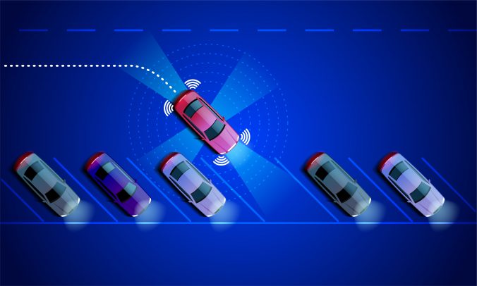
You know how it can be a real challenge to understand the complexity in emerging multi-modal and automated transport systems?
By harnessing Systems Engineering best practices, our Systems Engineers at the Connected Places Catapult (CPC) use their expertise in systems requirements gathering, safety management, and verification and validation, ensuring that all aspects and interactions in the AVP system are clearly defined, integrated, evaluated and tested, thus improving our ability to deliver a safe, efficient and innovative system.
Systems Engineering is an established practice capable of delivering technically complex systems, and Systems Engineers swear by the V lifecycle model, which shows the logical relationship between the different System Engineering activities.
In the V model, time and system maturity proceed from left to right:
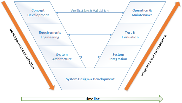
In each stage of the system life cycle, the Systems Engineering process iterates to ensure that a concept or design is feasible, and that the stakeholders remain supportive of the solution as it evolves.
The process is applied sequentially, one level at a time, adding additional detail and definition with each level of development.
1. Concept Development

The concept development is the first step of the life cycle of the AVP project. This stage explores concepts, identifies stakeholders’ needs and proposes viable solutions.
It includes activities such as:
• Concept of Operation (ConOps)
• Systems Engineering activity Plan
• Regulatory framework
2. Requirement Management
Requirements definitions are the key to success in the design and development of any complex system. Our Systems Engineers have carefully elicited requirements from all the project stakeholders to ensure the final product meets everyone’s needs, from technical feasibility to budget considerations and testability.
The total set of requirements encompasses the functional, performance, and non-functional requirements and the architectural constraints.
3. System Architecture

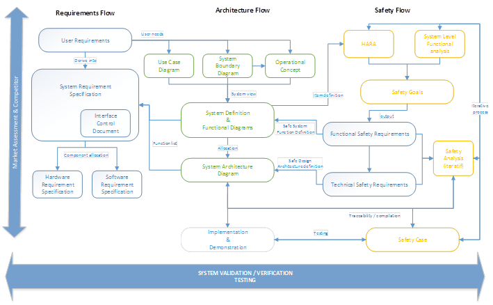
The architecture of a system is its fundamental structure. The purpose of drawing an architecture is to define a comprehensive solution based on principles, concepts, and properties logically related and consistent with each other. The architecture defines the system boundary and functions, from which more detailed system requirements can be derived.
This step of the cycle is focused on developing:
• System Level Architecture
• Functional Architecture
At the start of the AVP project, both of these architectures were drawn. The system level architecture refers more to the overall system and its operating environment. The functionalities that enable the AVP technology are mapped on the functional architecture, based on the Autoware ROS and showing modules such as perception, sensor fusion, path planning, and others.
4. System design and development
Once the initial opportunities and constraints have been identified in the steps above, it is time to create and describe in detail the AVP system to satisfy the identified needs.
While the Parkopedia Engineers work on developing the AVP system in accordance with the ConOps, Requirements and System Architecture, the Systems Engineers at the CPC focus on the functional system analysis and producing the Safety Case for the AVP testing.

This lifecycle step expands on ISO 26262, which addresses the functional safety in road vehicles. The analysis of the system level safety is carried through system-level functional analysis, such as the Failure Mode and Effect Analysis (FMEA) and the Hazard Risk Assessment (HARA) , which results in providing the system safety goals (translated as the safety requirements for the system). These form the system safety argument for the Safety Plan for the AVP project.
This step is crucial to ensure the risk is minimised if and when the system fails. Every malfunction leads to a warning and degradation strategy and the safety driver should be able to gain control of the vehicle.
Note: the system analysis also involves reviewing all of the previous deliverables as the design is being developed.
5. System Integration
The AVP system is made of different system elements provided by different parties:
– The vehicle is provided by StreetDrone
– The software, application and maps are provided by Parkopedia
– The localisation system is developed by the University of Surrey

This step ensures that all of the disparate system elements integrate to create an effective whole and allows the different teams to work in parallel confident that all of the pieces fit and work together.
The interface management activity relate to the steps taken to integrate the different architecture elements:
- Reviewing and refining the previously mentioned deliverables (ConOps, System Architecture, Requirements, FMEA, HARA)
- Assessing the criteria and methods for Requirements verification and validation (Analysis/Inspection/Test/Demonstration)
- The Interface Control Document (ICD), which describes the integration strategy of the AVP system. This is a live document and is continuously updated until the end of the system development and testing.
6. Test & Evaluation

Prior to driving in the desired environment, the vehicle has to demonstrate that it is capable of safely navigating and responding to diverse situations and scenarios, such as emerging pedestrians, vehicles, obstacles, etc. By combining simulation and testing in a real environment (open field track and car parks), the AVP system can be validated.
This step focuses on ensuring that the developed system is operationally acceptable and that the responsibility for the effective, efficient, and safe operations of the system is transferred to the owner.
- Can the system be tested, demonstrated, inspected, or analysed to show that it satisfies requirements?
- Are the requirements stated precisely to facilitate specification of system test success criteria and requirements

Testing will always be performed with a highly trained safety driver, who will monitor the vehicle behavior at all times and ready to take over in the event of a failure. An engineer will monitor the path on a HMI, so that the safety driver is not distracted. The system must be able to detect and respond to a wide range of static obstacles in the testing environment.
Prior to testing, some activities need to be completed to ensure the safety of the AVP system:
- Safety Plan
- Safety Case
- Risk Assessment and Method Statement (RAMS) (operational safety)
- Incident Reporting Template
Safety Plan
It examines the evidence required to show that acceptable safety has been achieved for any given testing activity, and how that evidence is to be collected, such that when all the evidence is taken together, there is a convincing argument that the project as a whole is safe.
Safety Case
It summarises the evidence collected prior to commencing Autonomous Valet Parking testing in accordance with the Safety Plan. There will be a Safety Case for each test phase: testing in a controlled environment (open field track), testing in car parks and the demonstration.
RAMS:
This document sets out the safety procedures that all participants are required to follow during testing of the autonomous control system and ensures the requirements and procedures are read and understood by all involved in the trial, and adhered to at all times. The Risk Assessment for the trial is also included in this document. Similarly to the Safety Case, each testing phase will be prepared with a RAMS.
After testing, the requirements are reviewed and given a pass/fail mark depending on the acceptance criteria set. In both cases, a justification needs to be provided.
Once again, the previous deliverables are reviewed and refined as required.
7.Operation and maintenance
The AVP system has now been tested in different test environments and settings. The system is ready to be deployed, and as part of this activity, several demonstrations are organised as evidence of the operational effectiveness of the deployed AVP system.
The Systems Engineers carry the below activities, verifying and validating the concept one last time:
- RAMS
- Safety Case close out
- Verification and Validation close out
- Review and refine as required previous deliverables
8. Conclusion
The self-driving car industry is a fast-moving and uncertain environment, which makes safety the number one priority. This is also why the AVP project consortium is encouraging the industry to work together, collaborate, share use-cases and lessons learnt. Self-driving cars have the potential to ensure safety of passengers, reduce road congestion, drive smarter and in a more sustainable way. By implementing a robust Systems Engineering process, the self-driving car industry can mitigate risks and drive society safely into the future.
Recent Comments