The Autonomous Valet Parking (AVP) project is a 30 month project funded by InnovateUK and the Centre for Connected and Autonomous Vehicles. It is scheduled to finish on 31 October 2020.
With more than three-quarters of the project timeline having passed, we are proud to say that we feel on track to achieve the project objectives within the allocated project time allowance, even with the current additional challenges of COVID-19 self-isolation restrictions.
Over the 5 objectives, the current status is as follows:
Develop automotive-grade indoor parking maps required for autonomous vehicles to localise and navigate within a multi-storey car park. Parkopedia believes this map-based approach is the best way to achieve global scale for the roll-out of an Automated Valet Parking feature, which is likely to be the first SAE level 4 feature. This goal is 100% achieved, as Parkopedia has collected data in a number of car parks around Europe and is creating an inventory of maps to be able to supply to customers. Some of these maps have been made available to the research community under a Creative Commons license.
Develop the associated localisation algorithms, targeting a minimal sensor set of cameras, ultrasonic sensors and inertial measurement units, that make best use of these maps. We have agreed to use Artificial Landmarks in the final demo for the project, and toward that effort this goal is 95% complete. Details about Artificial Landmarks and how they can be used for localisation are available in this blog post. For the remainder of the project the research effort will be directed towards localising with natural landmarks which is a much more difficult problem.
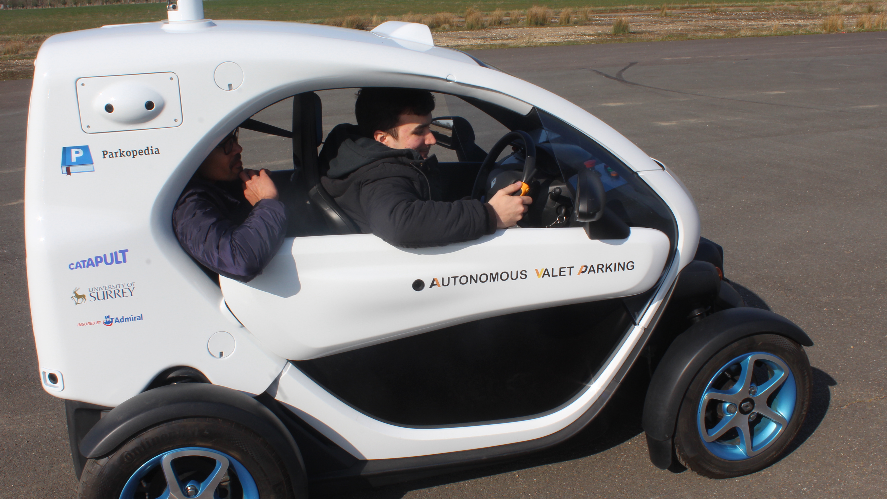
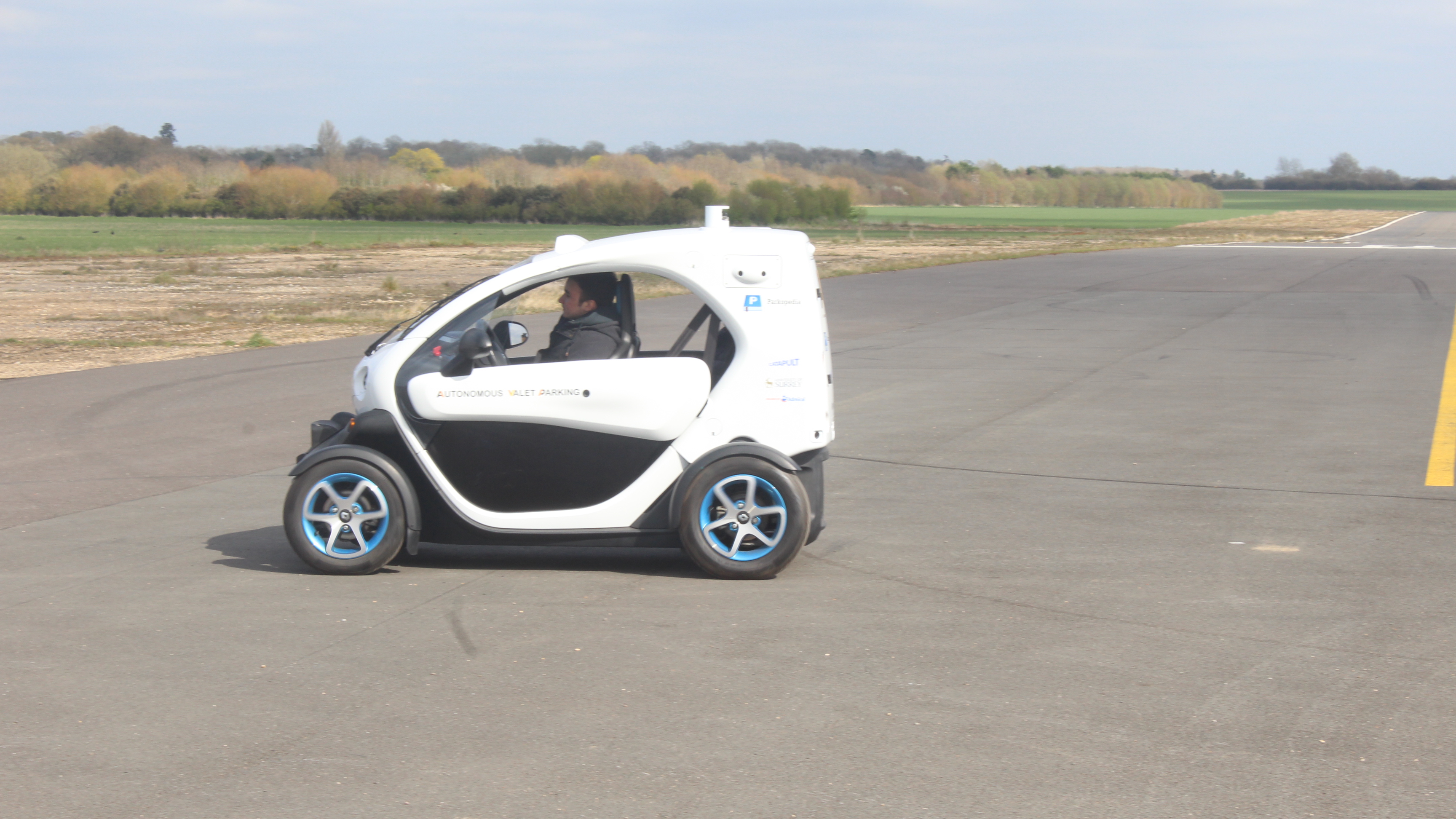
Demonstrate this self-parking technology in a variety of car parks. This is well underway, and the outstanding work items now exclusively relate to integration with the map and localisation algorithm. Great care is taken to account for car park ramps, as by necessity, the low concrete walls are at their closest to the car at this moment. These ramps are considered to be the point of greatest risk as the localisation methods have to work extra hard when moving between floor levels. Also, the vehicle control algorithms need to account for gravitational acceleration of the car down the slope, and slowing it on the up-slope. After a lot of testing in simulation and more than 250 hours of in-car testing, we are pleased to have overcome this challenge, which you can see in action in the video below.
Develop the safety case and prepare for in-car-park trials. Safety documents to cover the testing thus far have been published. A final document to cover demonstrations with large numbers of people is the last item outstanding. We have secured initial agreement for a final demonstration in a different car park to showcase the functionality.
Engage with stakeholders to evaluate perceptions around AVP technology. We have engaged with the wider public around this technology and the results have been published.
The project recently held the 7th (of 10) quarterly review meetings where demonstrated the vehicle’s capabilities to the project steering committee and stakeholders.
The outstanding work items now exclusively relate to integration with the map and localisation algorithm, but we are confident of completing the project on time with our objective achieved. We are looking forward to the day this feature is available in a production vehicle!
Localisation is a central problem in robotics and it is very relevant to the AVP project. A self-driving car that is looking for an empty parking slot must know where it is on a map. For a precise manoeuvre, such as parking, an equally precise map and localisation algorithm are required.
The AVP project also has to respect a realistic budget for sensors, which rules out LiDARs in favour of cameras and IMUs. For this reason the project is committed to develop a vision-based localisation solution that uses HD Maps. Vision-based localisation however is very difficult and no one has yet demonstrated a system that works accurately and robustly in a fully general environment.
Within the International Standards Organisation, Technical Committee 204, Working Group 14, Parkopedia is part of a drafting team that is developing a standard for Automated Valet Parking Systems. The drafting team has agreed on the requirement for Artificial Landmarks, i.e. fiducial markers to be manually positioned in a carpark to enable accurate, robust localisation. At minimum, artificial landmarks are necessary around the pick-up and drop-off and zones to initialise the localisation system of a vehicle equipped with AVPS.
The next section will give an overview of localisation with landmarks.
Background to localisation with landmarks
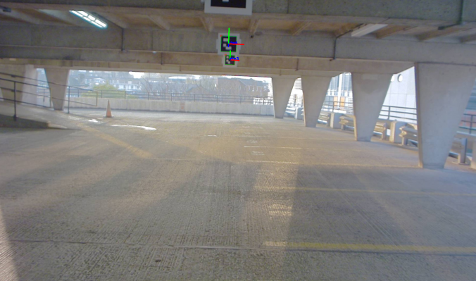
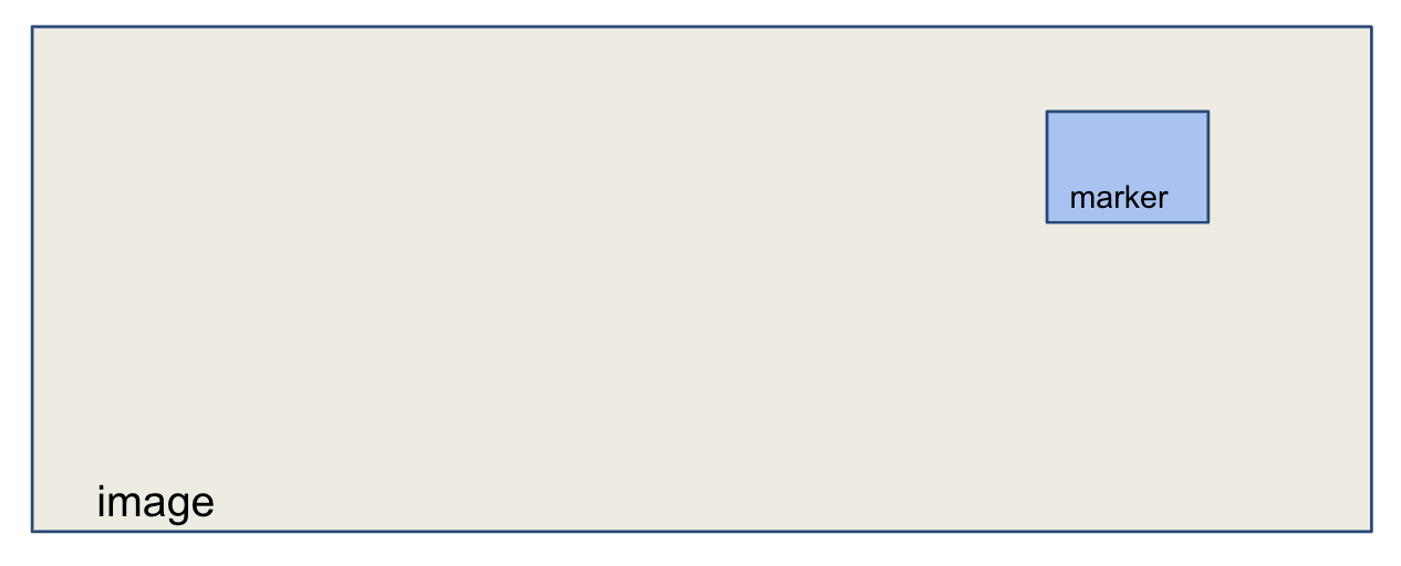
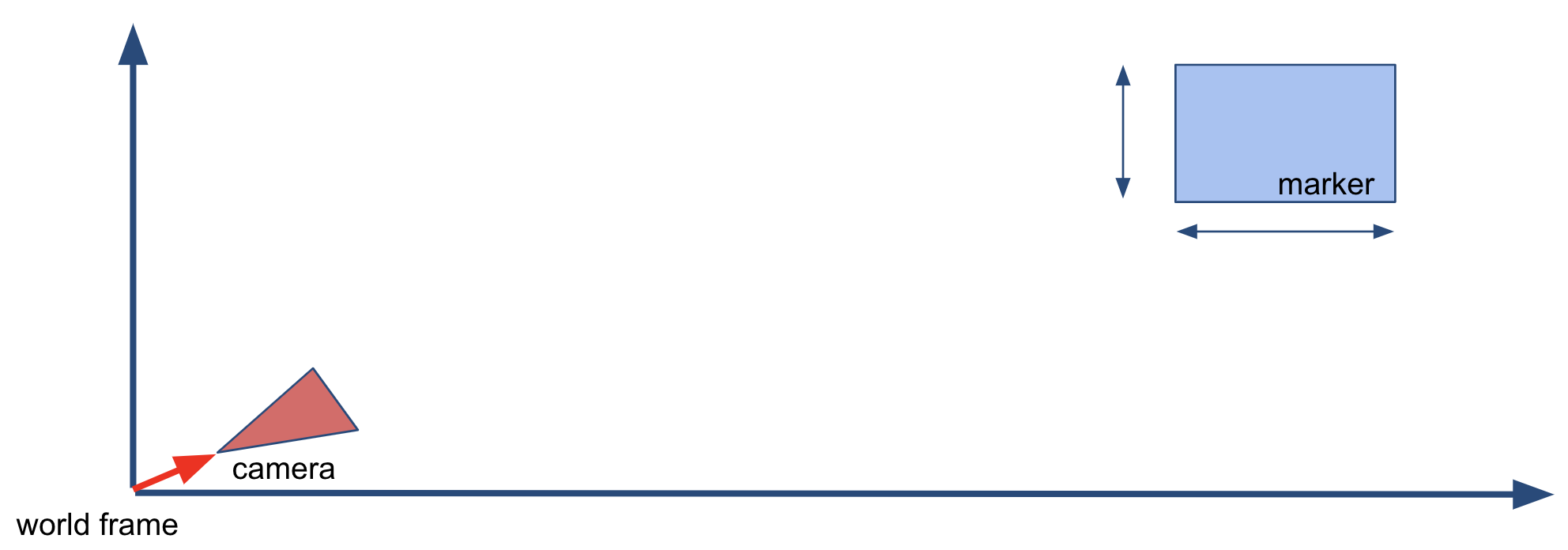
The first step of localisation with landmarks consists of detecting the landmark with the available sensors. In this example we are using a camera, so we need to find the pixel coordinates of a landmark in an image. Note that we use interchangeably the terms landmark and marker.
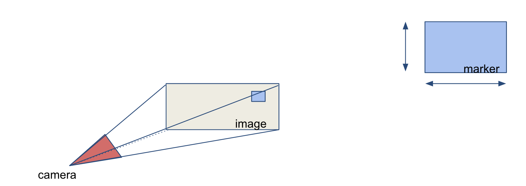
The second step is to estimate the sensor position with respect to the landmark. In the case of a calibrated camera and of a marker with known size, a single image is sufficient to estimate the rigid transformation between the camera and the marker. The algorithm used is a variation of Perspective-n-Point.
The third and last step is to estimate the pose of the camera in map frame. We know the position of the camera with respect to the marker from step 2. Provided that the marker is distinctively identifiable, we can find its position in the map. By chaining the two transformations, we obtain the desired pose of the camera in map frame.
Artificial Landmarks
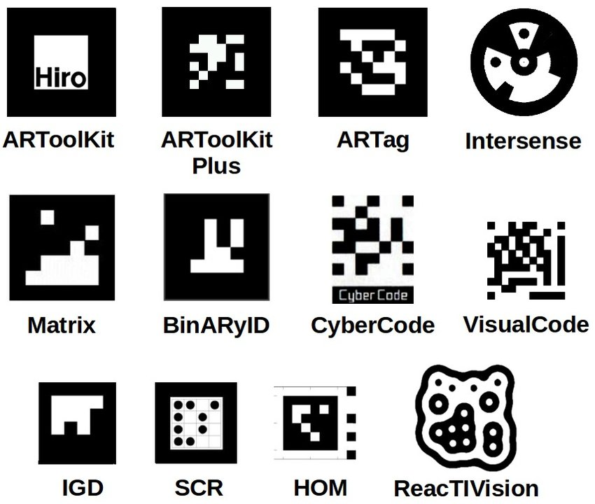
There are many designs for artificial landmarks in literature.
Given the localisation process outlined in the previous section, we know some requirements for a good landmark. It must be easy to detect to facilitate the first step. It must be distinctive enough to be told apart from the other landmarks. And finally it has to be of a size and shape easy to handle in practice.
There is a convergence to a black and white square shape marker because its properties:
High contrast
Simple geometry
Easy to encode information
High contrast and square shape are clearly useful in detection because they can be exploited by established computer vision techniques. For example thresholding or line detection.
The information encoding part has more degrees of freedom that can be used differently, keeping in mind the goal of having highly distinguishable landmarks.
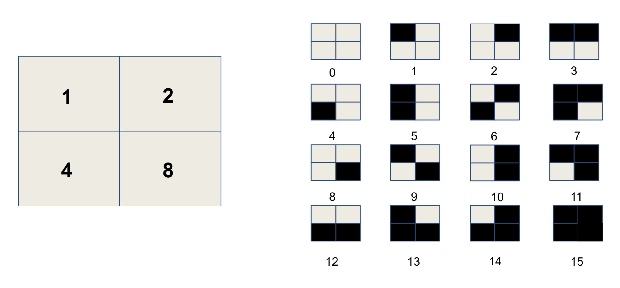
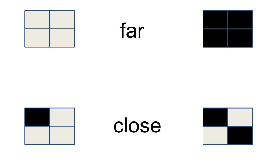
The basis of all the approaches is to subdivide the marker in a grid of small squares and use a binary encoding. That is to assign a power of two to each square, that is selected or not based on whether the square is black of white. By using a 2×2 grid we can represent 16 values as shown in the image below.
If we were to use all the possible markers for a given grid size, we would have the problem of erroneous detections. Some markers are very similar and minor occlusions or image noise could confuse the detection process. There are mainly two ways to deal with this problem, both of them based on the idea of sacrificing some information to achieve greater safety.
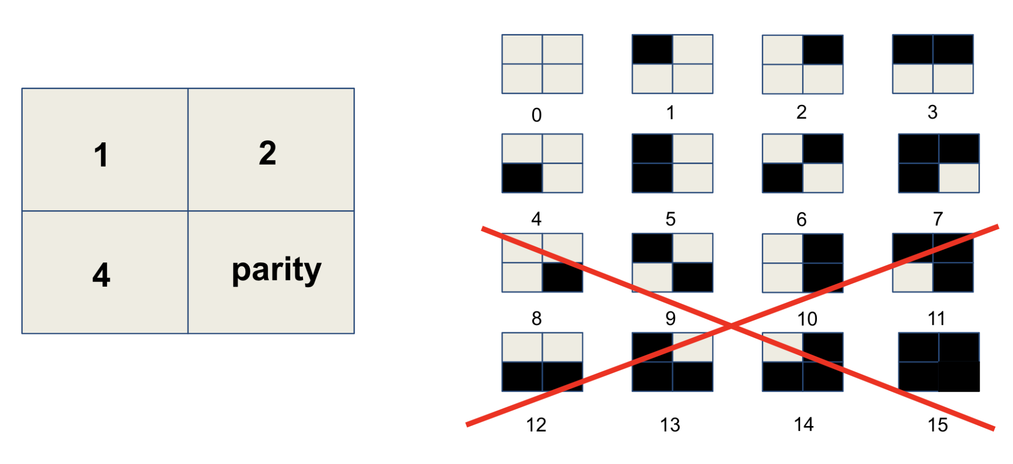
The first of these strategies is to set some squares to error detection. These squares convey no information on the id of the marker, but act as a necessary condition for correctness. The use of parity bits is widely studied in information theory and different schemes are available with different properties.
The second strategy is to maximize entropy, that is the distance between markers. Intuitively two markers with no square in common are far, while a marker is maximally close to himself. This notion is formalized by the concept of Hamming distance, which is also a widely studied topic in information theory.
The next two sections will analyze two marker types: ArUco and the standard proposed by the ISO drafting team.
ArUco markers
ArUco markers are a state of the art fiducial marker system explicitly designed for localisation.
The information encoding is designed for optimal intramarker distance. Possible markers are iteratively sampled and only the ones with a sufficiently large Hamming distance are selected.
ArUco is very flexible as it provides multiple dictionaries with different sizes. The authors of the paper provide a production grade implementation in OpenCV that also has Artificial Reality capabilities, very useful for debugging.
The following code snippet is an example of the use of a the Aruco library for localisation.
// Retrieve image of environment with Aruco marker cv::Mat input_image = /* retrieve image from camera */; // Initialise predefined dictionary DICT_4X4_250 auto dictionary = cv::aruco::getPredefinedDictionary(DICT_4X4_250); // Initialize MarkerVector struct, output parameter of the detection function MarkerVector markers; // Detect markers in the image cv::aruco::detectMarkers(input_image, dictionary, markers.corners, markers.ids); // Initialize camera intrinsics cv::Mat K = /* camera matrix */; cv::Mat D = /* distortion coefficients */; // Set marker size float marker_size = /* marker size including black border */ // Estimate marker pose cv::aruco::estimatePoseSingleMarkers(markers.corners, marker_size, K, D,markers.rotations, markers.translations);
We provide a downloadable with the PDF version of the ArUco dictionary DICT_4X4_250. An A2 version, more suitable for printing, is also provided for convenience. It is common to print the markers on waterproof PVC and mount them on 3mm plastic or aluminum.
ISO markers
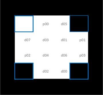
The AVPS drafting team has chosen to use a custom definition for artificial landmarks that explicitly encodes the orientation, data bits and parity bits for error checking. This encoding can be seen in the image below. Rotation is encoded through the four corner squares, with the top left white and remaining 3 black. With the orientation fixed, 8 data and 4 parity bits are encoded with the remaining 12 bits to create a Hamming Code.
It is possible to create custom dictionaries in OpenCV to use with the ArUco library. We have encoded the ISO dictionary as a custom one in a single header file which you can just include in your software.
Only one line of code from the previous example has to change – the creation of the dictionary – then the same code can be used to detect ISO markers.
auto dictionary = cv::makePtr<cv::aruco::Dictionary>(iso::generateISODictionary());
By using the library in this straightforward way, we see a lot of false positives, because we are not using the error correcting properties of the Hamming codes. A first step to improve the situation is to set the detector parameter errorCorrectionRate to zero, to disable the default correction done by ArUco. A better solution, that uses the full potential of the Hamming codes, requires to modify the ArUco detection algorithm.
As in the case of ArUco, we provide PDFs of the ISO dictionary as 30×30 cm squares and in A2 format.
Conclusion
A reasonable question to be asking right now is whether all this information above is even necessary. Can we not enable localisation without artificial landmarks?
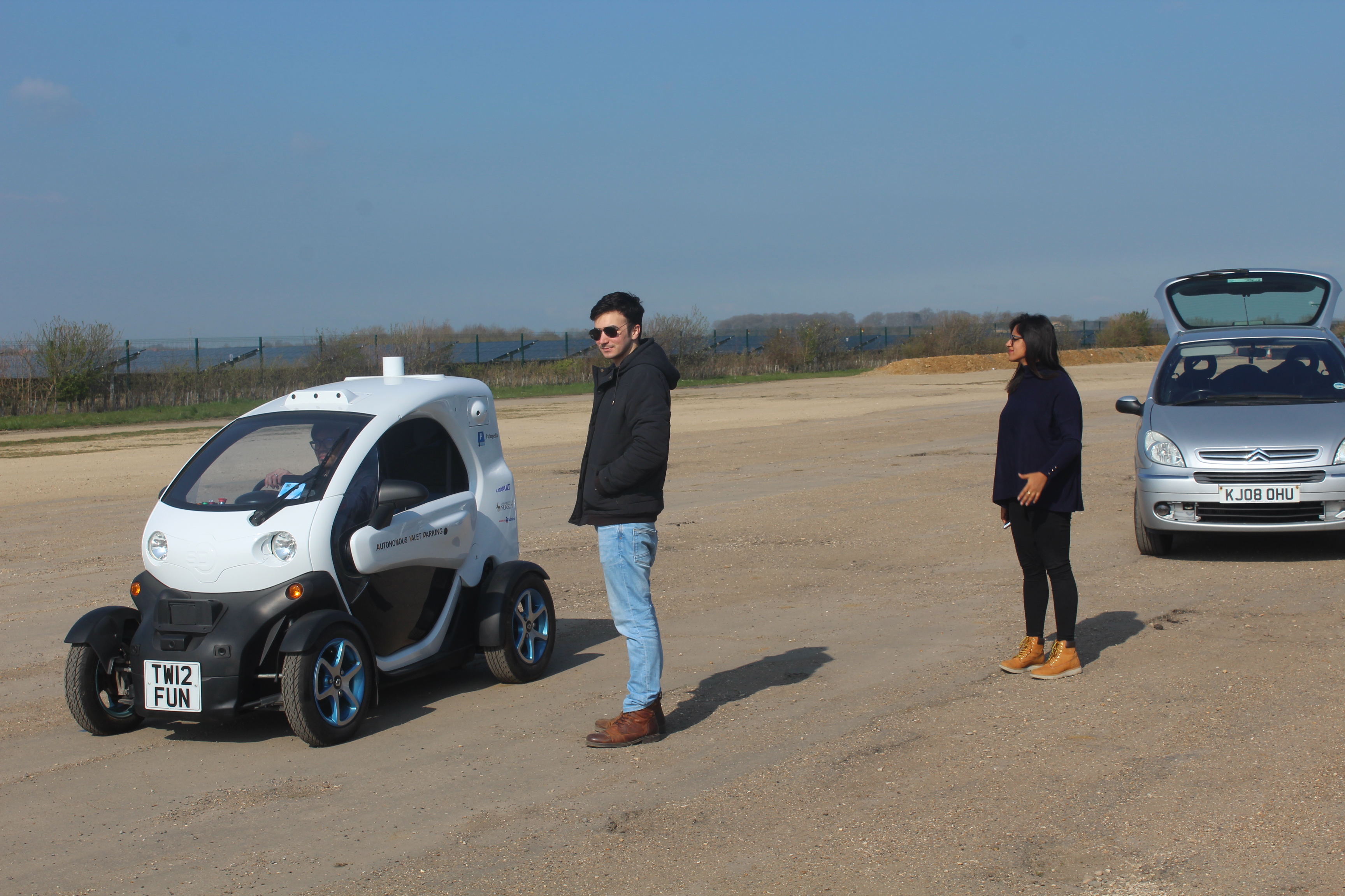
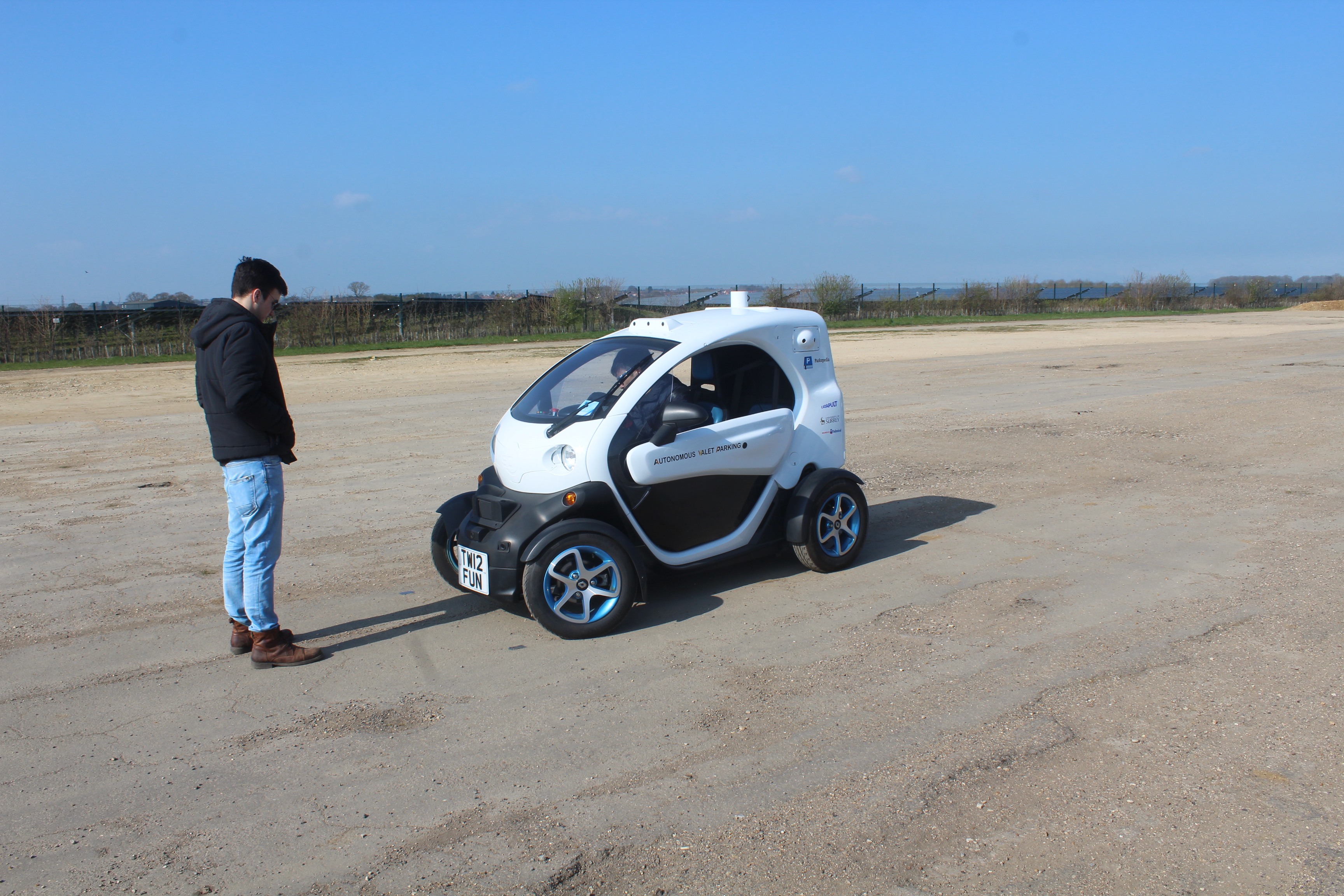
It turns out that this is a difficult problem and industry is looking for a solution. The University of Surrey is developing a vision-based localisation algorithm that avoids the use of Artificial Landmarks as part of the AVP project and we look forward to demonstrate this technology on the AVP StreetDrone.
Expect to see a StreetDrone parking itself autonomously soon!
One of the main objectives of the AVP project is to create maps of car parks. Parkopedia is committed to working with our Open Source partners through the Autoware Foundation and have therefore released 3 maps of car parks to the community under the Creative Commons 4.0 BY-SA-NC license.
The maps are designed to be machine readable and are supplied in the OpenStreetMap XML format. This format is widely used and forms the basis for the OpenStreetMap mapsthat anyone can contribute to using tools such as the Java Open Street Map editor.
Our maps are designed to be useful for Automated Driving, which is why we’ve decided to make use of the Lanelet library as the data model for maps within the Autonomous Valet Parking prototype vehicle.
You can download the maps here and the following code can be used to plan a path using the lanelet library.
# libs
import lanelet2
import lanelet2.core as lncore
# load the map, for example autonomoustuff
osm_path = os.path.join(os.path.dirname(os.path.abspath('')), "AutonomouStuff_20191119_134123.osm")
print("using OSM: %s (exists? %s)" % (osm_path, os.path.exists(osm_path)))
# load map from origin
lorigin = lanelet2.io.Origin(37.3823636, -121.9091568, 0.0)
lmap = lanelet2.io.load(osm_path, lorigin)
# ... and traffic rules (Germany is the sole location, for now)
trafficRules = lanelet2.traffic_rules.create(lanelet2.traffic_rules.Locations.Germany, lanelet2.traffic_rules.Participants.Vehicle)
graph = lanelet2.routing.RoutingGraph(lmap, trafficRules)
# create routing graph, and select start lanelet and end lanelet for the shortest Path
startLane = lmap.laneletLayer[2797] # lanelet IDs
endLane = lmap.laneletLayer[2938]
rt = graph.getRoute(startLane, endLane)
if rt is None:
print("error: no route was calculated")
else:
sp = rt.shortestPath()
if sp is None:
print ("error: no shortest path was calculated")
else:
print [l.id for l in sp.getRemainingLane(startLane)] if sp else None
# save the path in another OSM map with a special tag to highlight it
if sp:
for llet in sp.getRemainingLane(startLane):
lmap.laneletLayer[llet.id].attributes["shortestPath"] = "True"
projector = lanelet2.projection.MercatorProjector(lorigin)
sp_path = os.path.join(os.path.dirname(osm_path), os.path.basename(osm_path).split(".")[0] + "_shortestpath.osm")
lanelet2.io.write(sp_path, lmap, projector)
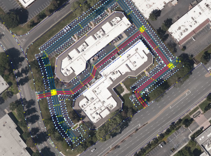
# now display in JOSM both, and you can see the path generated over the JOSM map
# Ctrl+F --> type:relation "type"="lanelet" "shortestPath"="True"
# and the path will be highlighted as the image below
The Autonomous Valet Parking project is a 30-month project funded by InnovateUK and the Centre for Connected and Autonomous Vehicles, due to end on 31 October 2020. We are five quarters in and a lot has been achieved:
We have created our first maps of car parks which we are trialling with customers,
The vision-based localisation algorithms are well advanced,
The autonomous software to power our StreetDrone is ready to take out for a demo,
The safety case has ensured that we are in a position to demo this safely.
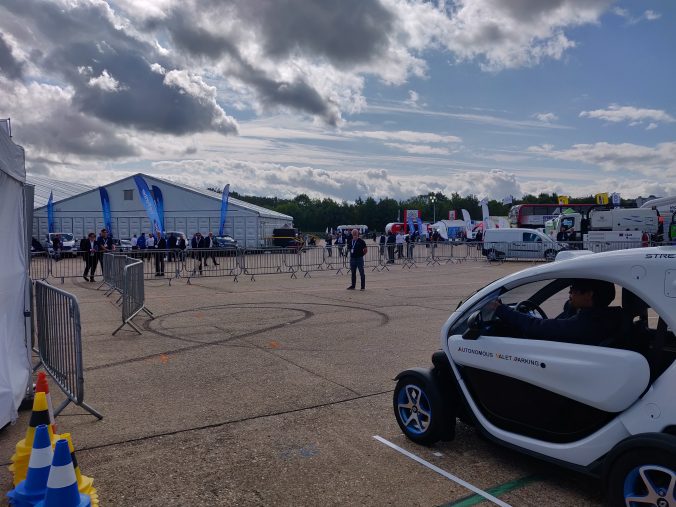
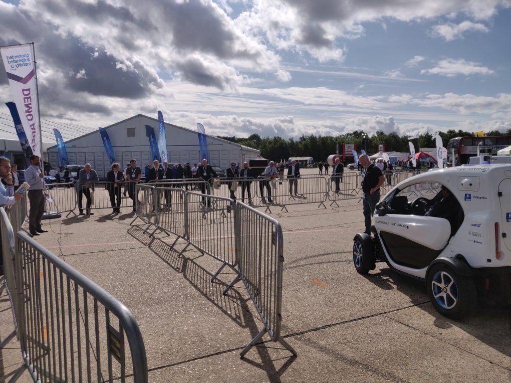
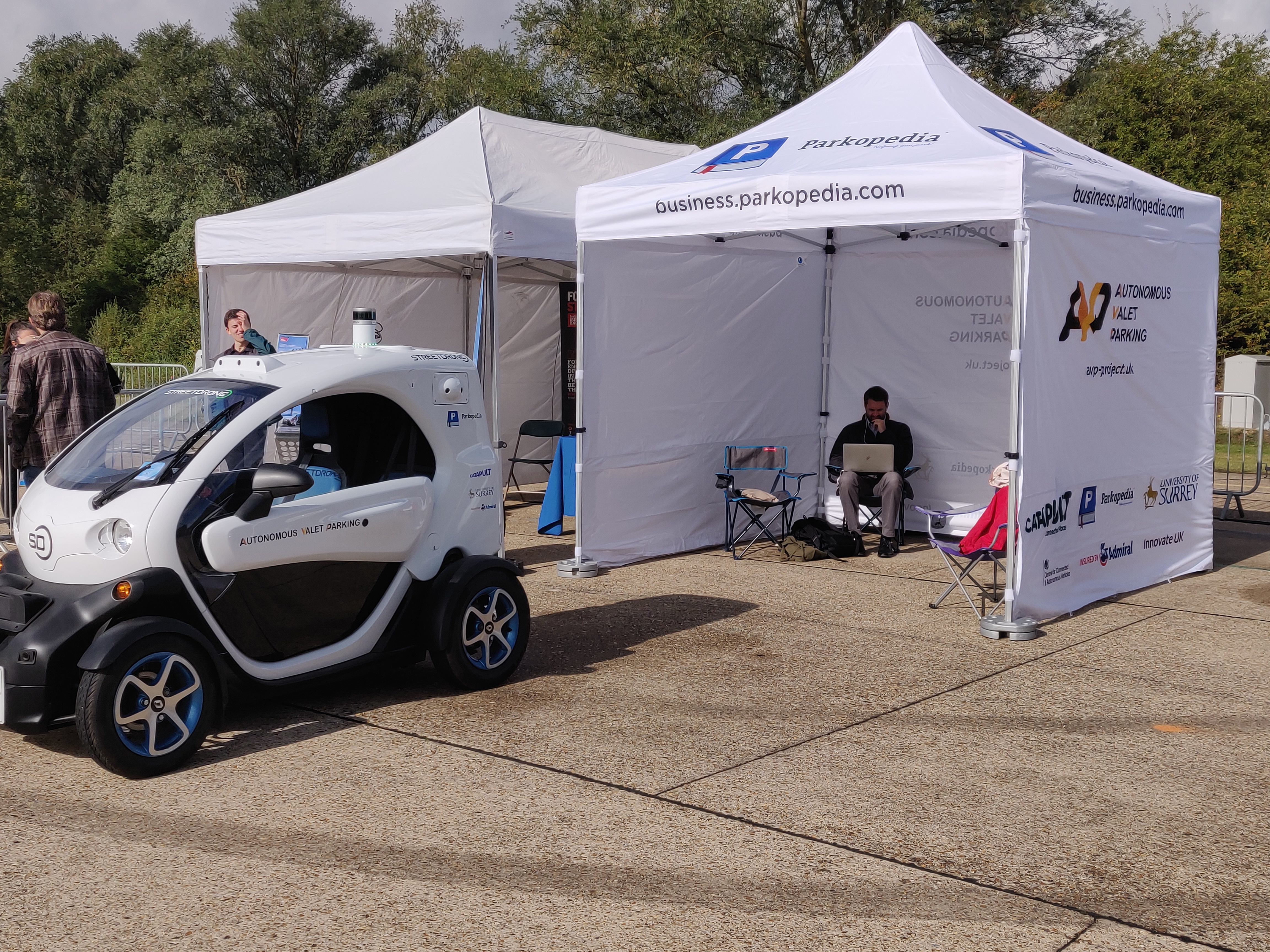
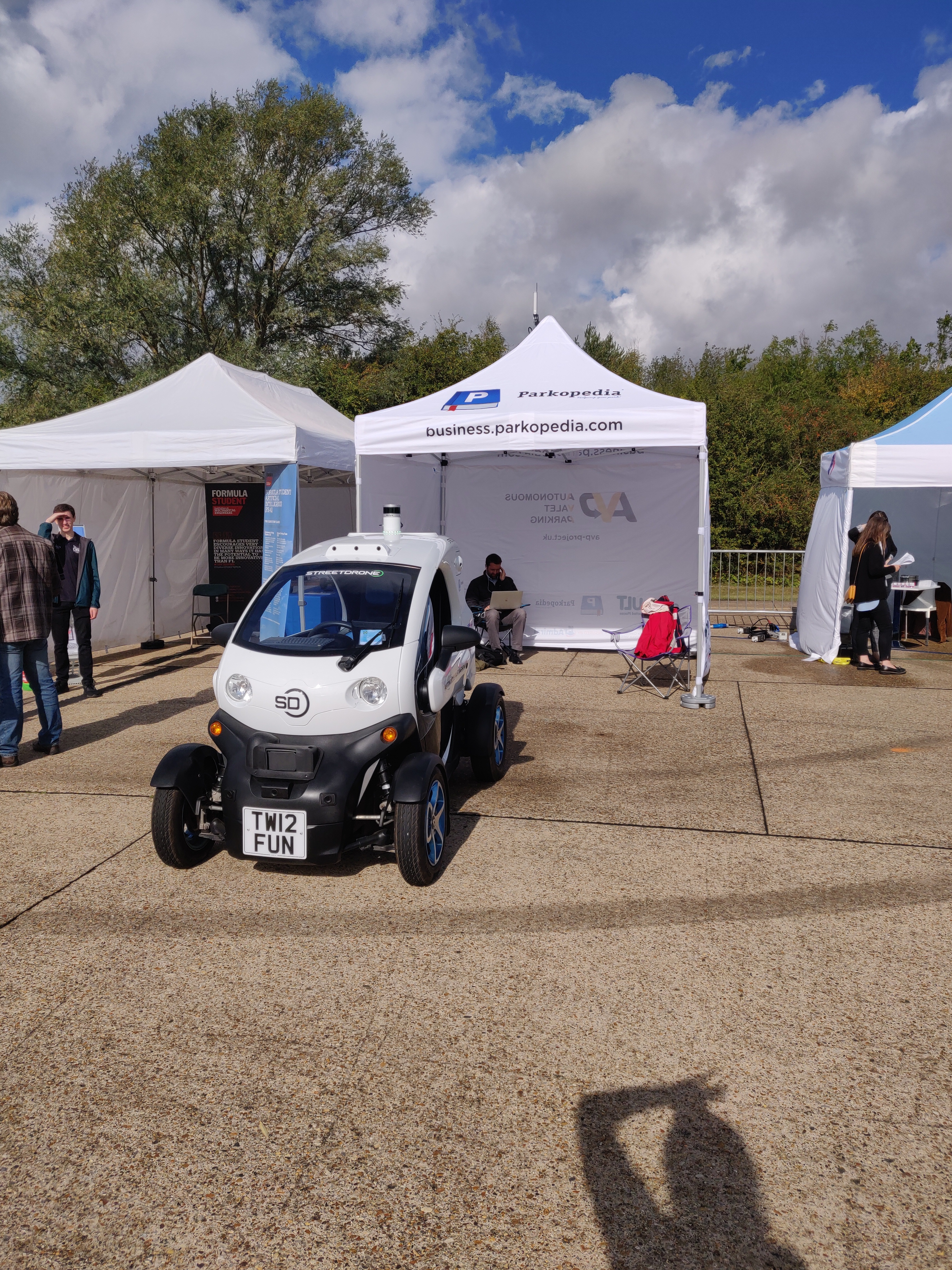
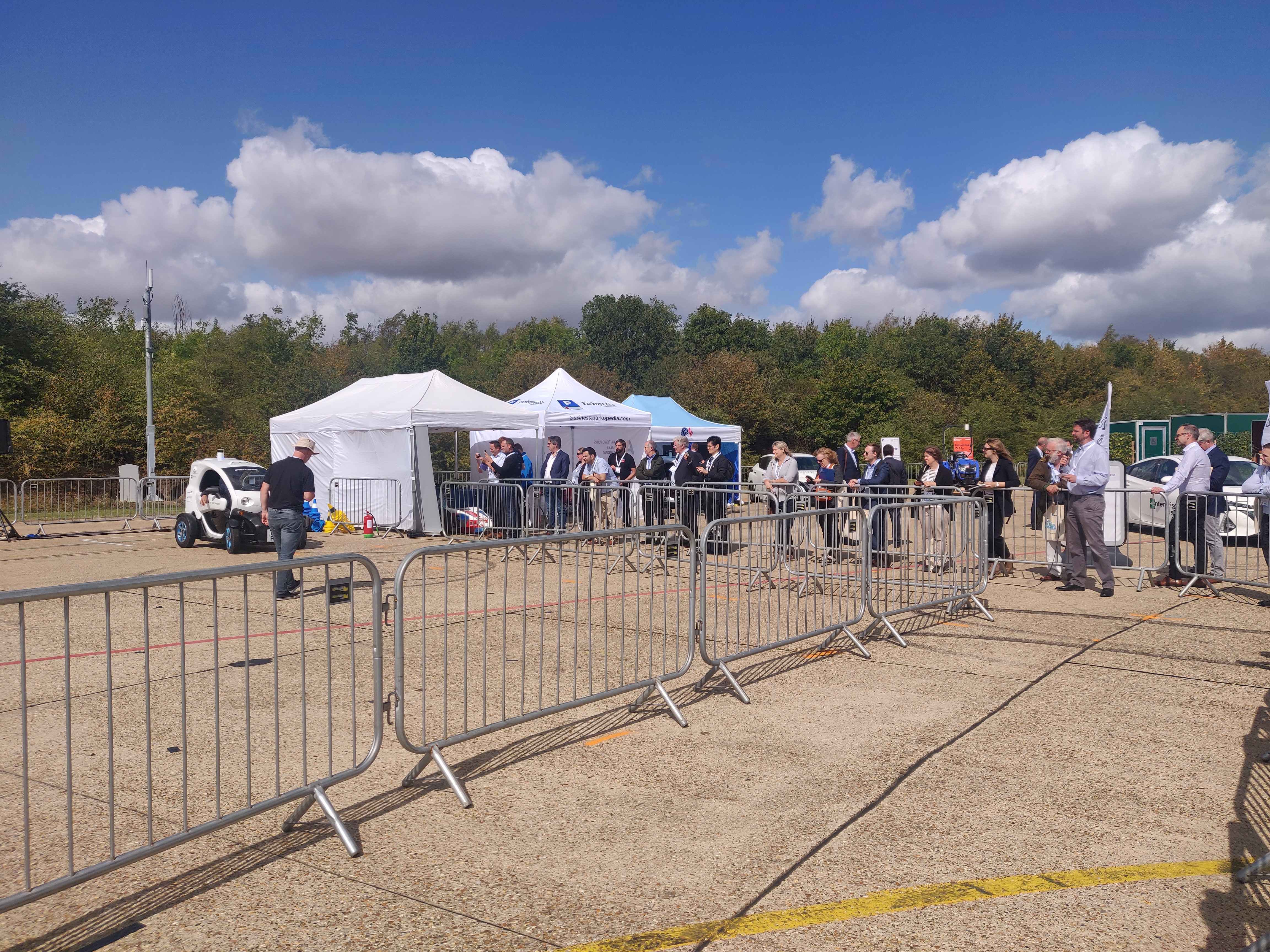
At the CENEX-CAM event that took place at Millbrook Proving Ground UK 4-5 September 2019, we showed the progress made in the project at this halfway point. The main objective was to demonstrate that the Autoware-based software on the StreetDrone is able to control the vehicle by following waypoints consistently and accurately. The demonstration scenario consisted of three parts and reflects how we believe AVP will be used in real life. In the demo, you can see:
The vehicle following a pre-defined set of waypoints to the designated parking spot, having been dropped off at a designated drop-off zone by its driver,
The vehicle exiting the parking spot and driving to the pick-up zone (where the vehicle’s regular driver would collect it),
A test of our automatic emergency braking, using the front-centre ultrasonic sensor on the vehicle.
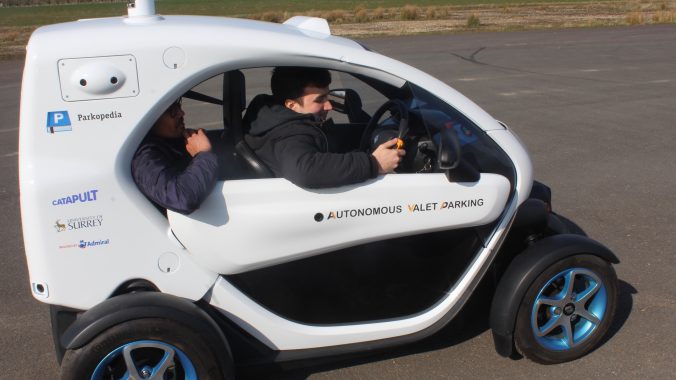
This public demo was an important milestone for us to demonstrate our ability to control the vehicle using a PID controller for longitudinal (throttle) control and pure-pursuit for lateral (steering) control.
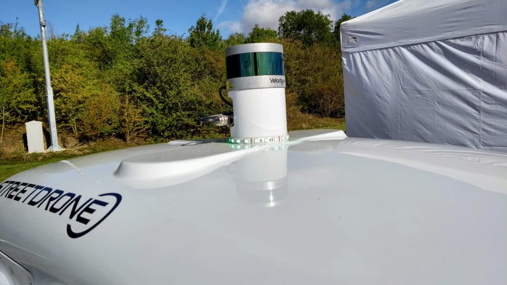
Localisation is done using the LiDAR with NDT matching. At this stage of the project we’ve limited the speed to 1m/s, this will double to 2m/s (5mph) in the future.
We are using the SAE convention for marking lamps, with green for manual control, blue when under autonomous control and red when an error state occurs. Adding the RGB LED lighting was done alongside the development work to enable switching between forwards and reverse in software while still in autonomous mode.
The safety case for the project combines operational and system safety. On the operational side we have a safety driver who can take over when a dangerous situation presents, and we also have system safety using the LiDAR and ultrasonic sensors, which will bring the vehicle to a stop to avoid driving into a hazard. We demonstrated Automated Emergency Braking using the ultrasonic sensor, following the testing and preparation done previously at Turweston.
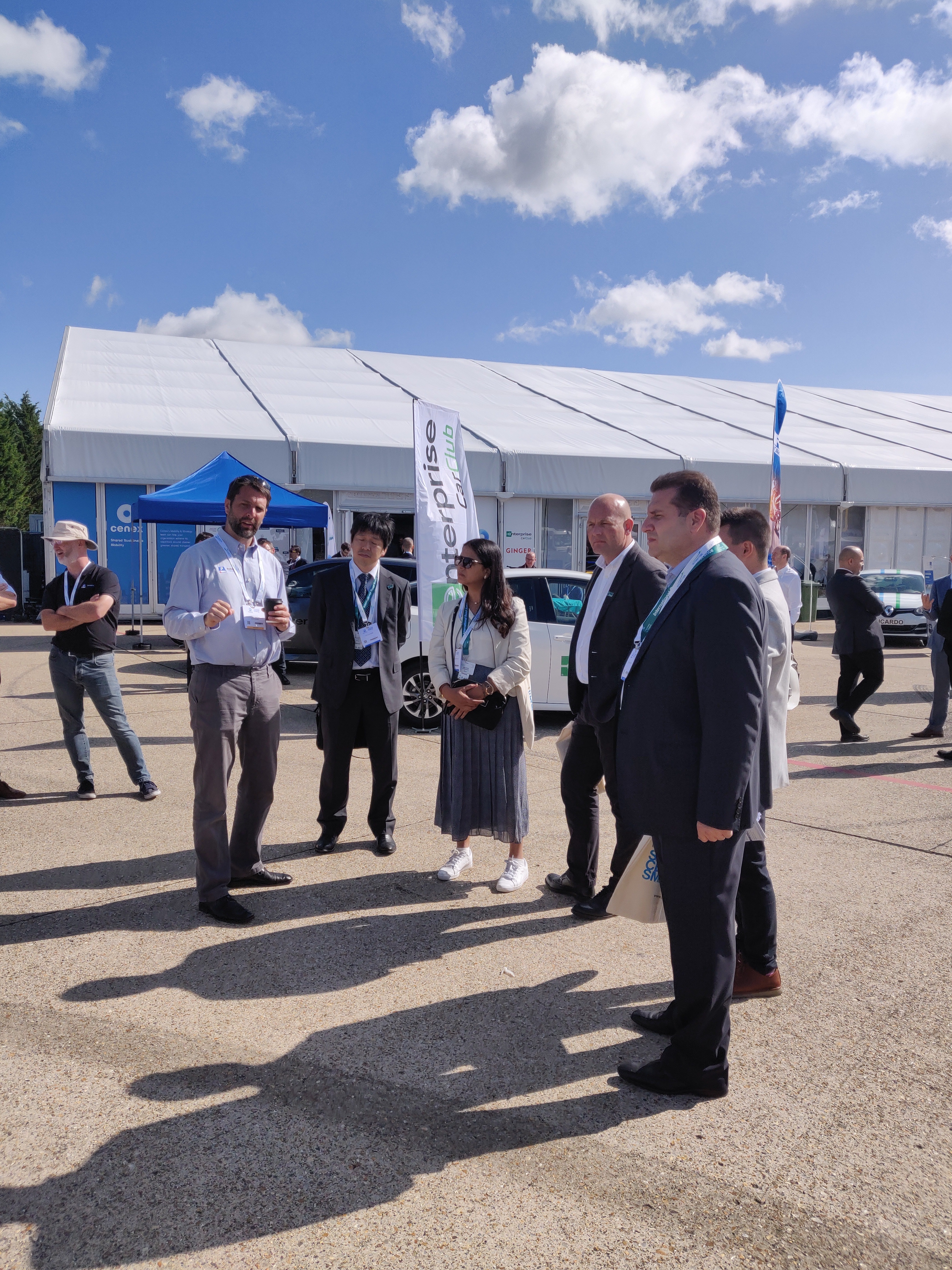
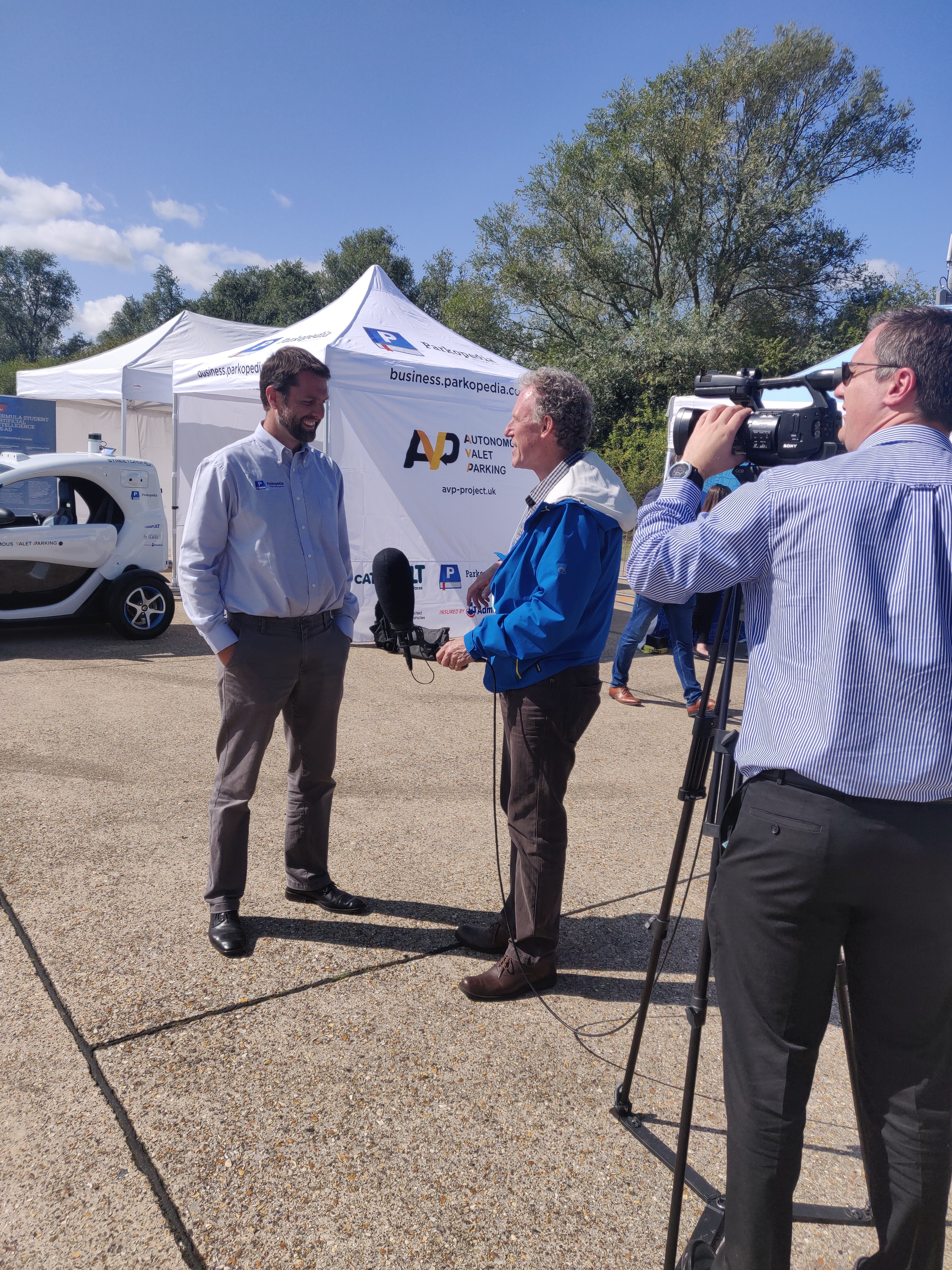
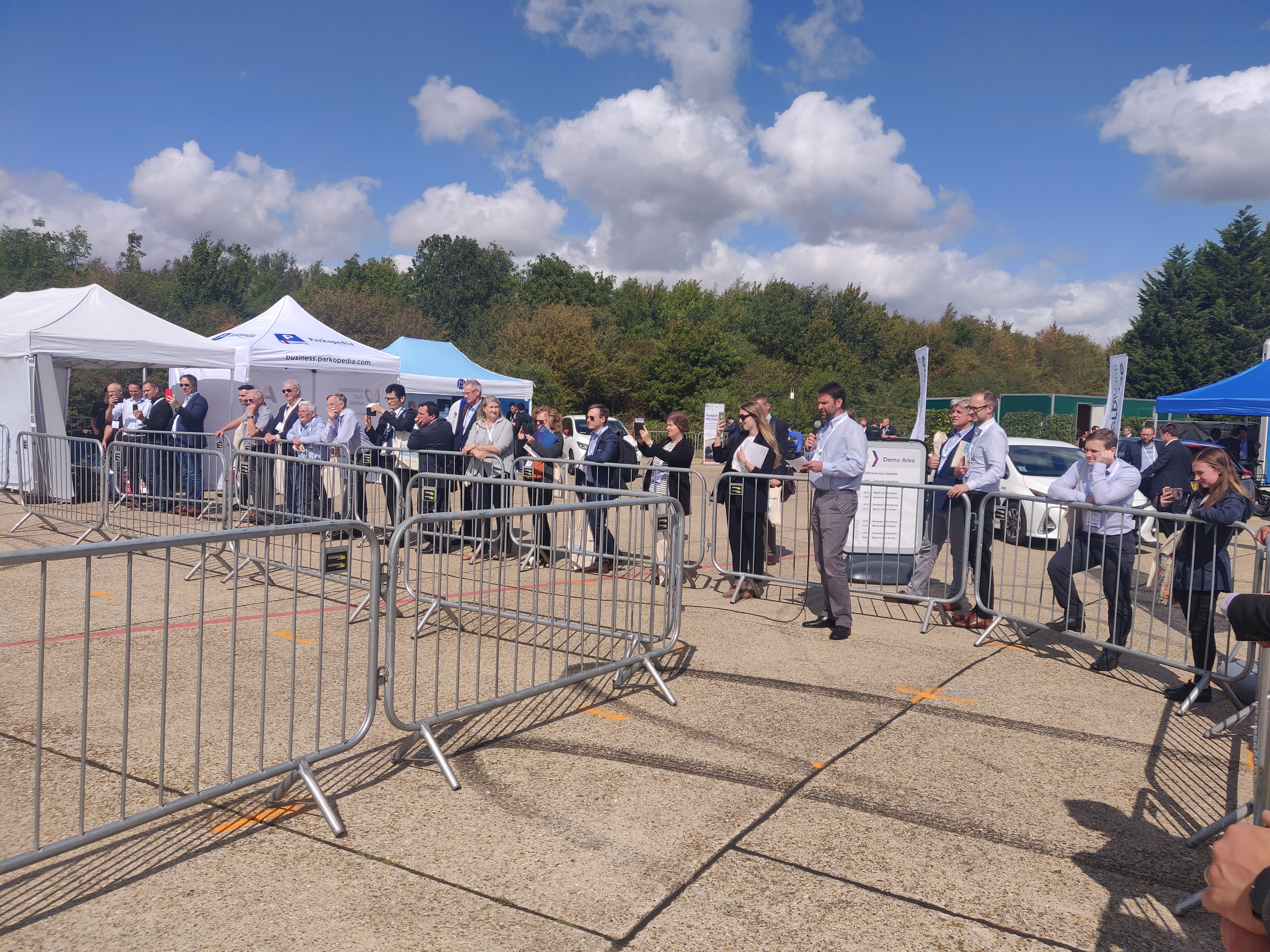
Overall, the demo (done five times in two days) was well received, and we saw good levels of interest from delegates at the event, with lots of questions being asked about the project. It was a pleasure to speak to media and to delegates.
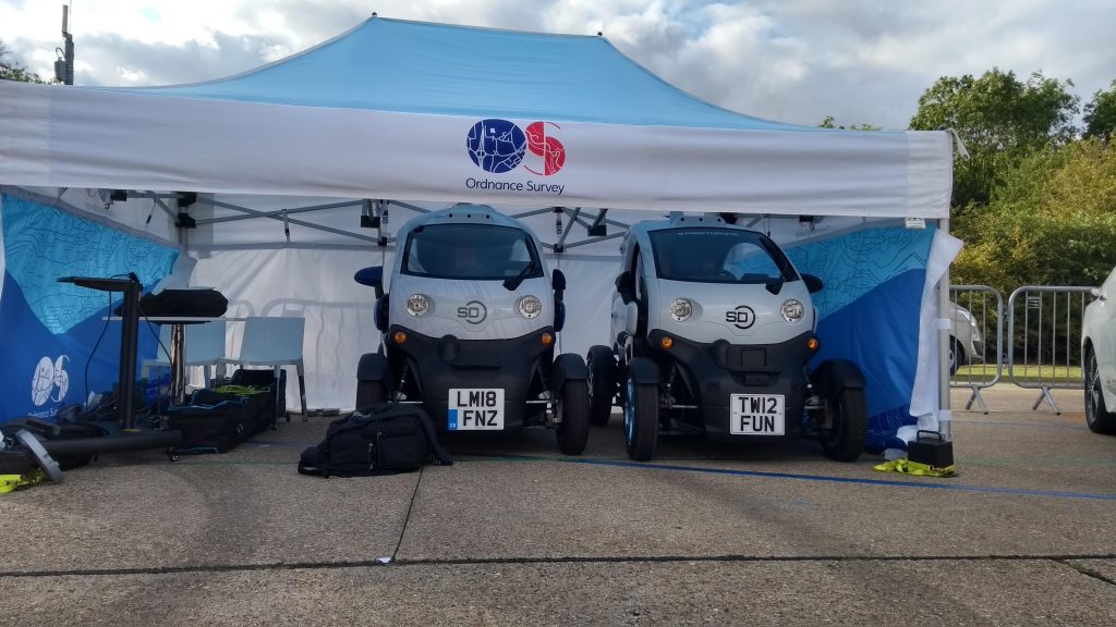
We’ve learned a lot from our friends at Ordnance Survey and we look forward to hosting them and others at the upcoming Autoware Hackathon. Many thanks to them of all the help and for storing our StreetDrone overnight under their gazebo!
Over the remaining 13 months of the project, we will be working on navigation and localisation using maps, with a final demonstration of the end solution due to take place in Autumn 2020.
IV2019 brings together researchers and practitioners from universities, industry and government agencies worldwide to share and discuss the latest advances in theory and technology related to intelligent vehicles.
The Autoware foundation is hosting a workshop on Sunday 9th June 2019, with the aim of discussing the current state of development of Autoware AI and Autoware Auto, and considering various technical directions that the Foundation is looking to pursue. Parkopedia’s contribution is around maps and specifically, the integration of indoor maps for Autonomous Valet Parking.
Parkopedia’s Angelo Mastroberardino will be presenting our work on maps, answering questions like “Why do we need these maps?”, “How do we represent geometry and road markings within maps?”, and naturally leading towards the question of how we use these maps for path planning within indoor car parks.
Later, Dr Brian Holt will be joining Tier 4, Apex.AI, Open Robotics, TRI-AD, and Intel on a panel to discuss Autoware and its impact on autonomous driving.
Parkopedia joined the Autoware Foundation as a premium founding member, because we believe in open source as a force multiplier to build amazing software. We are contributing maps, including for the AutonomouStuff car park in San Jose, USA, which you can download for use with your own self-driving car in simulation. Find out more
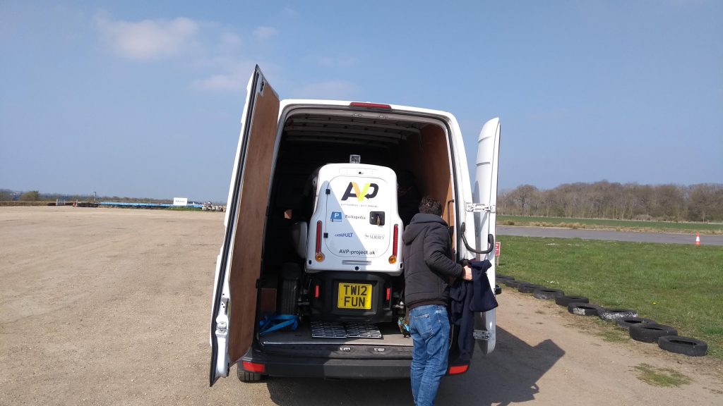
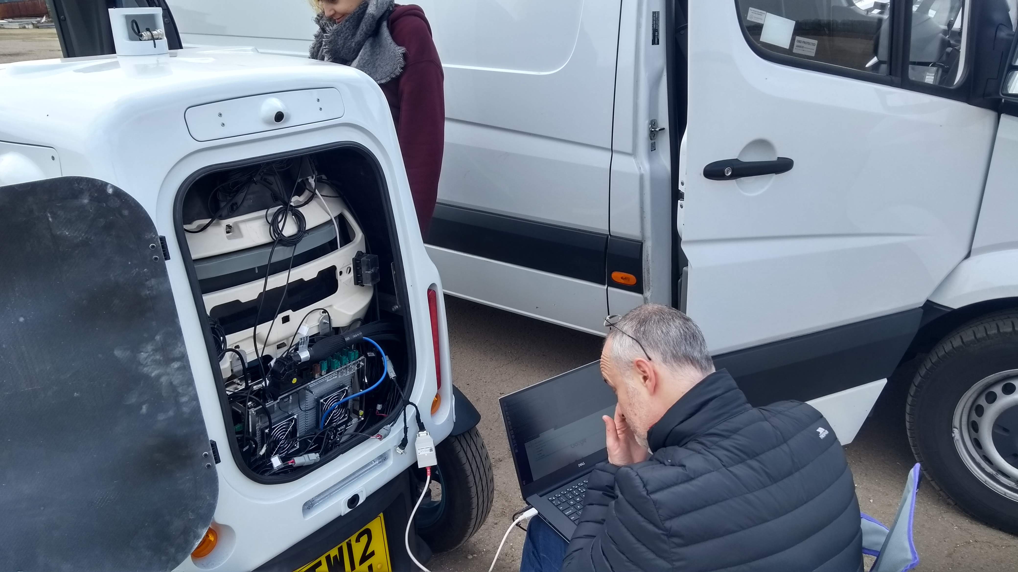
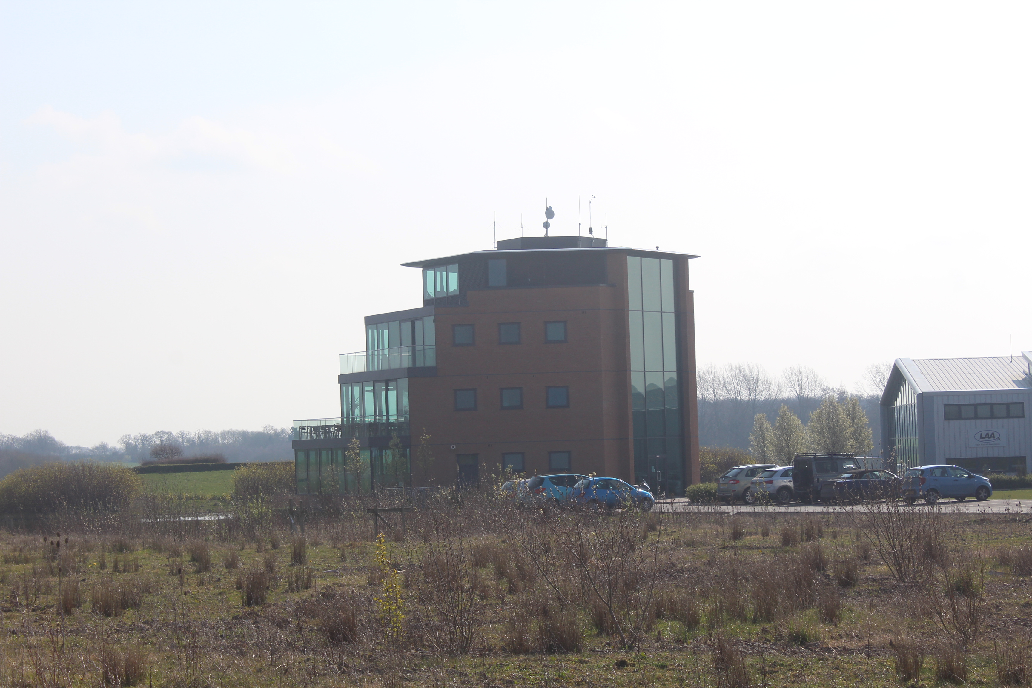
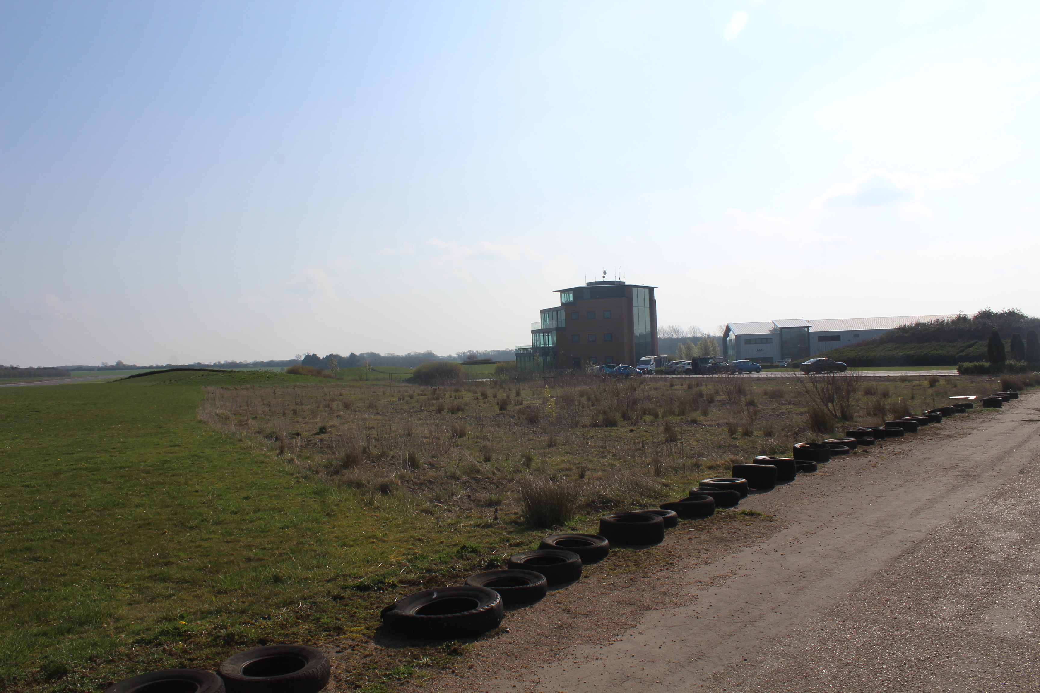
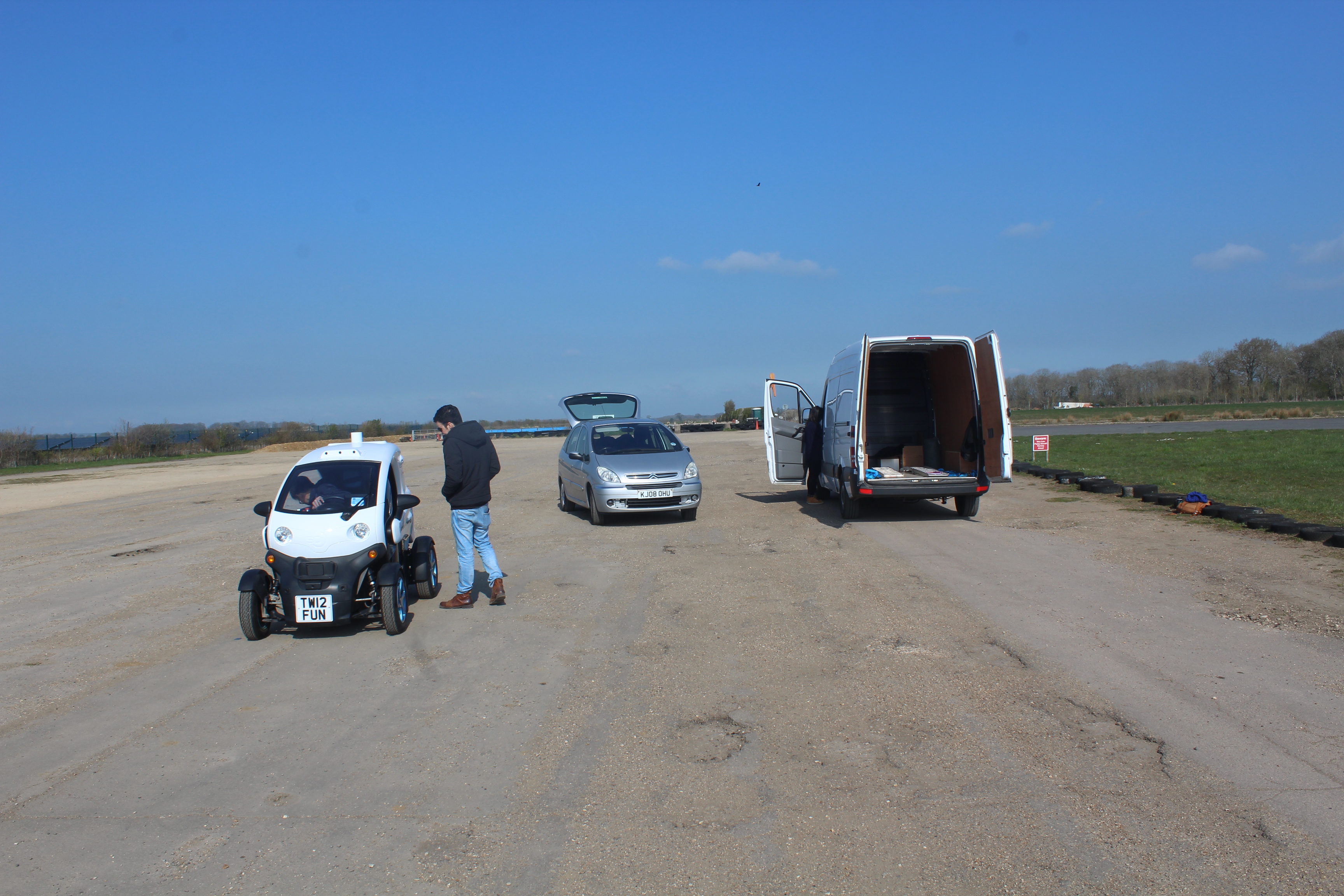
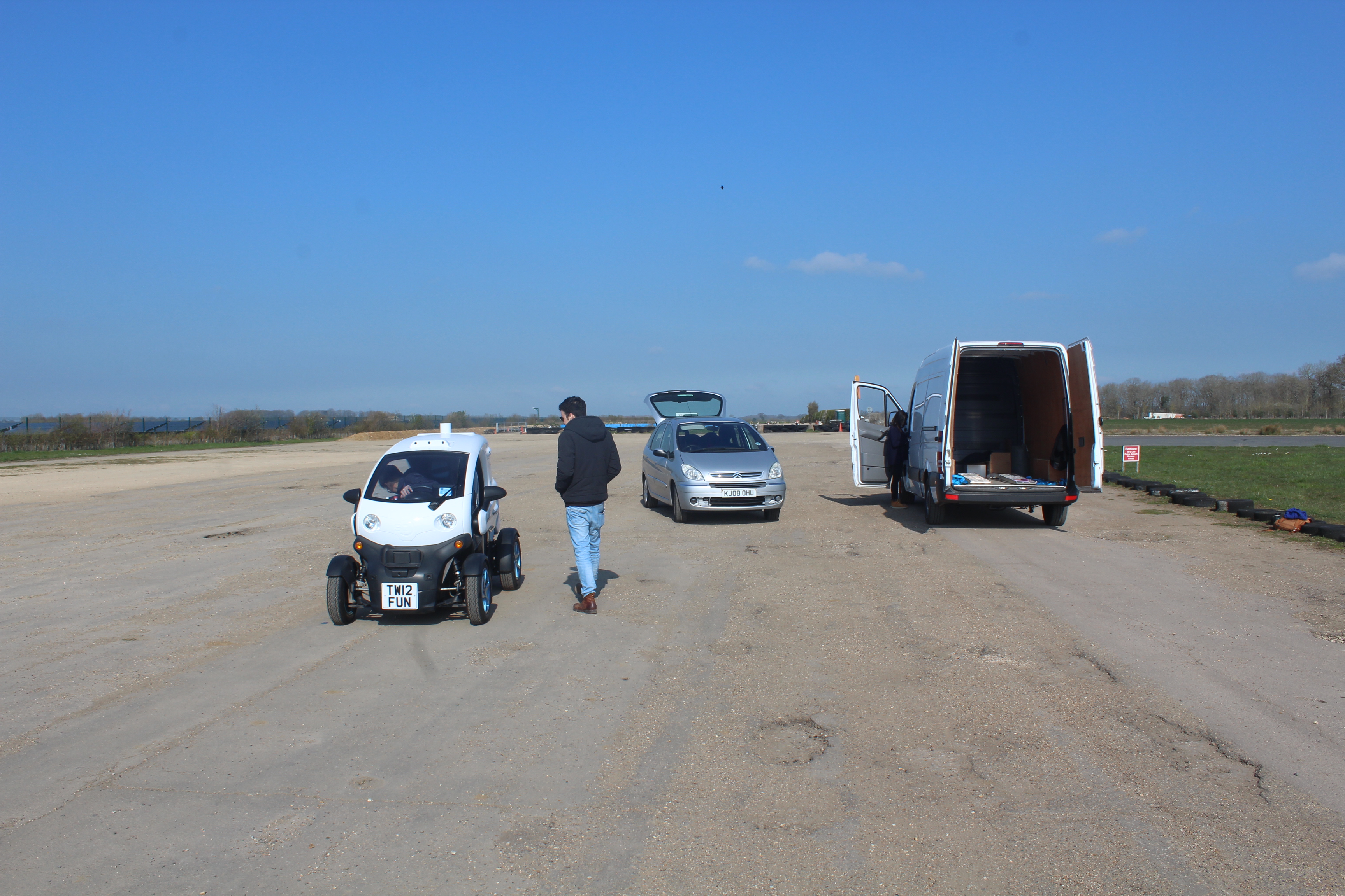
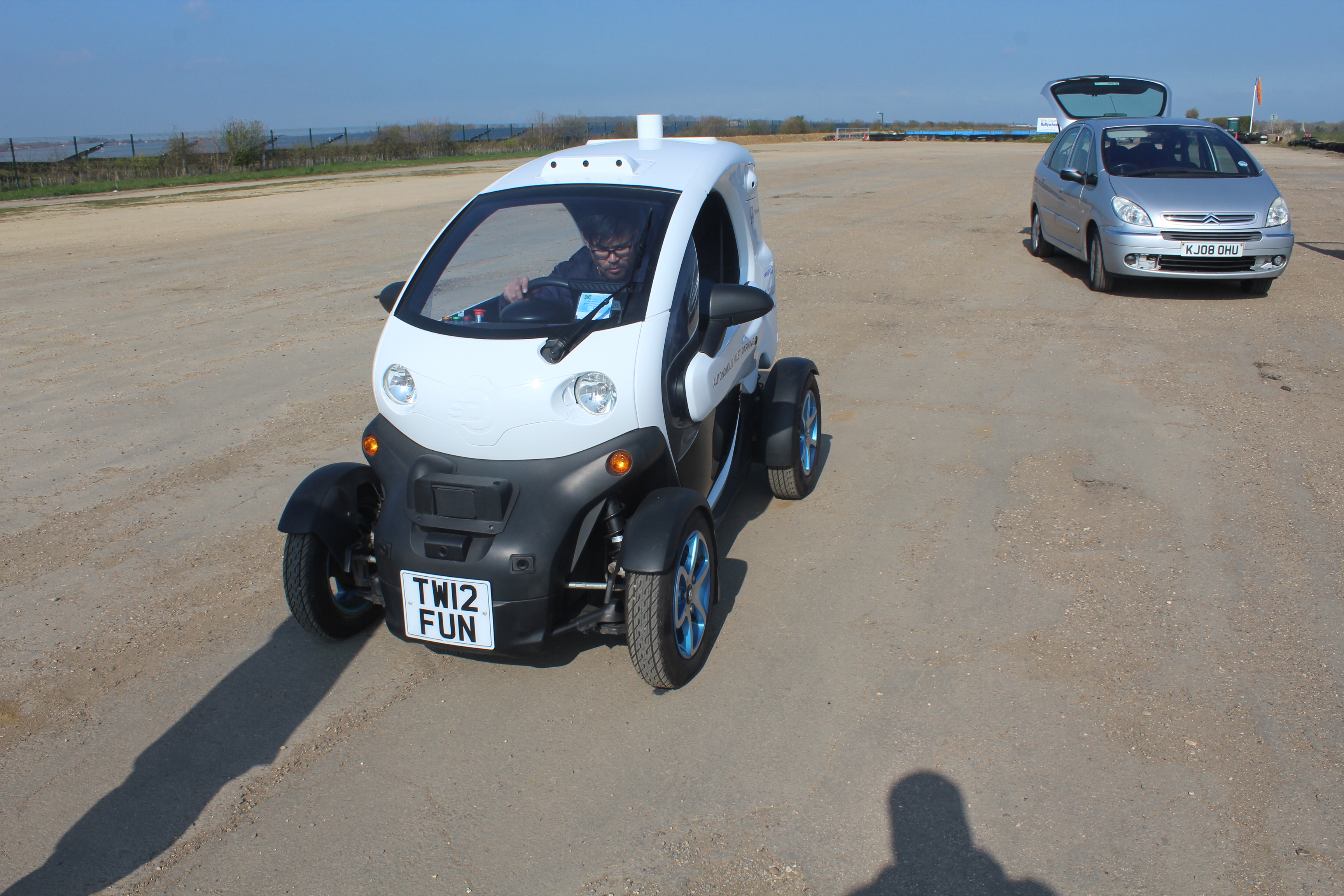
We successfully completed our first tests at Turweston Aerodrome last week.
Unloading the StreetDrone.ONE
The plan was to check and ensure the robustness of the drive-by-wire system, to train our safety drivers and to do basic path following.
We also took the opportunity to collect some data from the ultrasonic sensors that are on the StreetDrone.ONE which we will use for system safety.
Ultrasonic data collectionDrive-by-wire testing
For testing the drive-by-wire system, we carried out a number of test runs using teleoperation from the driver. We drove on the track forward, backward and changing steering at various speeds. The system performed satisfactorily. We also performed a full brake test to work out a safe driving speed and stopping distance in a case of emergency stop. Further details are presented in this blog post.
Path following with PID feedback control and a basic GPS and IMU localisation
On the final day, we tested a basic path following to make sure everything worked together. We integrated the drive-by-wire (dbw) system with a path follower, PID motion controller and a basic gps and imu localisation in this open space environment.
We managed to achieve the objective of testing the dbw with the feedback control for the path following. However, precision was not there as we expected. The basic imu and gps sensor localisation would not give very accurate positioning and tends to drift away or jump around to within 5m accuracy. To resolve this issue, we are working on a better localisation using RTK GPS (like a simpleRTK2B) using RTK corrections over NTRIP.
Our next test will focus on path following using the high quality localisation and we also hope to start with path planning within the open space. More updates will follow!


Recent Comments